The toolbar at the top of the editing pane provides the
main functions of the pane. The default tool is the
Select tool (![]() ).
In general button 1 click on any tool selects a tool for one
use, before reverting to the default tool, and button 1 double
click selects a tool for repeated use.
).
In general button 1 click on any tool selects a tool for one
use, before reverting to the default tool, and button 1 double
click selects a tool for repeated use.
The tools fall into four categories.
Layout tools. Provide assistance in laying out artifacts on the diagram.
Annotation tools. Used to annotate artifacts on the diagram.
Drawing tools. Used to add general graphic artifacts to diagrams.
Diagram specific tools. Used to add UML artifacts specific to a particular diagram type to the diagram.
Some of the tools that are generally not all used so often, are combined in a dropdown, to take less space on the toolbar. See e.g. Figure 11.3, “The drawing tools selector.”. Press the symbol at the right of the tool to pop it open. These drop-down tools remember their last used tool persistently. This means that when ArgoUML starts, they show the last tool that was activated the previous time ArgoUML was run.
The following two tools are provided in all diagrams in this category.
 Select. This tool provides for general
selection of artifacts on the diagram. Button 1 click
will select an artifact. CTRL with button 1 can be used
to select (or deselect) multiple artifacts. Button 1
motion will move selected 2D items or add and move a new
control point on a link. Button 1 motion on a selected
component's control point will stretch that
component's shape.
Select. This tool provides for general
selection of artifacts on the diagram. Button 1 click
will select an artifact. CTRL with button 1 can be used
to select (or deselect) multiple artifacts. Button 1
motion will move selected 2D items or add and move a new
control point on a link. Button 1 motion on a selected
component's control point will stretch that
component's shape. Broom. Button 1 motion with this
tool provide a “broom” which will sweep all
artifacts along. This is a very shortcut way of lining
things up.
Broom. Button 1 motion with this
tool provide a “broom” which will sweep all
artifacts along. This is a very shortcut way of lining
things up.The Broom can also be invoked by using SHIFT with button 1 motion when the Select tool is in use.
The Broom is discussed at length in its own chapter, see Section 11.4, “The Broom”
![[Tip]](images/tip.png) | Tip |
|---|---|
Additional control of artifact layout is provided through the Arrange menu (see Section 9.7, “The Arrange Menu”). | |
The annotation tool Comment (
![]() )
is used to add a comment to a selected UML artifact.
)
is used to add a comment to a selected UML artifact.
![[Caution]](images/caution.png) | Caution |
|---|---|
Unlike most other tools you use the Select tool to select an artifact, and then button 1 click on Comment to create the comment. If no element is selected when the comment tool is clicked, then the comment is created and put at the left top corner. | |
The comment is created alongside the selected artifact, empty by default. The text can be selected with button 1 double-click and edited from the keyboard.
The UML standard allows comments to be attached to any artifact.
You can link any comment to aditional elements using
the CommentLink (
![]() )
tool.
)
tool.
These are a series of tools for providing graphical additions to diagrams. Although they are not UML artifacts, the UML standard provides for such decoration to improve the readability of diagrams.
| Tip |
|---|---|
These drawing tools provide a useful way to partially support some of the UML features (such as general purpose notes) that are missing from the current release of ArgoUML. | |
Eight tools are provided, all grouped into one drop-down widget. See Figure 11.3, “The drawing tools selector.”. Button 1 click on the diagram will place an instance of the graphical item of the same size as the last one placed. The size can be controlled by button 1 motion during placement. One side or end of the element will be at button 1 down, the other side or end at button 1 up. In general after they are placed on the diagram, graphical elements can be dragged with the Select tool and button 1 and re-sized by button 1 motion on the handles after they have been selected.
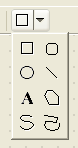
 Rectangle. Provides a rectangle.
 Rounded Rectangle. Provides a
rectangle with rounded corners. There is no control over
the degree of rounding.
Rounded Rectangle. Provides a
rectangle with rounded corners. There is no control over
the degree of rounding. Circle. Provides a circle.
 Line. Provides a line.
 Text. Provides a text box. The text is
entered by selecting the box and typing. Text is centered
horizontally and after typing, the box will shrink to the
size of the text. However it can be re-sized by dragging
on the corners.
Text. Provides a text box. The text is
entered by selecting the box and typing. Text is centered
horizontally and after typing, the box will shrink to the
size of the text. However it can be re-sized by dragging
on the corners. Polygon. Provides a polygon. The
points of the polygon are selected by button 1 click and
the polygon closed with button 1 double click (which will
link the final point to the first point).
Polygon. Provides a polygon. The
points of the polygon are selected by button 1 click and
the polygon closed with button 1 double click (which will
link the final point to the first point). Spline. Provide an open spline. The
control points of the spline are selected with button 1
and the last point selected with button 1 double
click.
Spline. Provide an open spline. The
control points of the spline are selected with button 1
and the last point selected with button 1 double
click. Ink. Provide a polyline. The points
are provided by button 1 motion.
Ink. Provide a polyline. The points
are provided by button 1 motion.
Several tools are provided specific to UML artifacts on use case diagrams. The detailed properties of these artifacts are described in the section on use case diagram artifacts (see Chapter 16, Use Case Diagram Artifact Reference).
 Actor. Add an actor to the diagram.
For convenience, when the mouse is over a selected actor
it displays two handles to left and right which may be
dragged to form association relationships.
Actor. Add an actor to the diagram.
For convenience, when the mouse is over a selected actor
it displays two handles to left and right which may be
dragged to form association relationships. Use Case. Add a use case to the
diagram. For convenience, when the mouse is over a
selected use case it displays two handles to left and
right which may be dragged to form association
relationships and two handles top and bottom which may be
dragged to form generalization and specialization
relationships respectively.
Use Case. Add a use case to the
diagram. For convenience, when the mouse is over a
selected use case it displays two handles to left and
right which may be dragged to form association
relationships and two handles top and bottom which may be
dragged to form generalization and specialization
relationships respectively. Association. Add an association
between two artifacts selected using button 1 motion
(from the first artifact to the second). There are 6
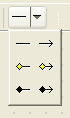
types of association offered here, see
Figure 11.4, “The association tool selector.”:
association,
aggregation and composition,
and all these three can be
bidirectional or
unidirectional.
Association. Add an association
between two artifacts selected using button 1 motion
(from the first artifact to the second). There are 6
types of association offered here, see
Figure 11.4, “The association tool selector.”:
association,
aggregation and composition,
and all these three can be
bidirectional or
unidirectional. Dependency. Add a dependency between
two artifacts selected using button 1 motion (from the
dependent artifact).
Dependency. Add a dependency between
two artifacts selected using button 1 motion (from the
dependent artifact). Generalization. Add a generalization
between two artifacts selected using button 1 motion
(from the child to the parent).
Generalization. Add a generalization
between two artifacts selected using button 1 motion
(from the child to the parent). Extend. Add an extend relationship
between two artifacts selected using button 1 motion
(from the extended to the extending use case).
Extend. Add an extend relationship
between two artifacts selected using button 1 motion
(from the extended to the extending use case). Include. Add an include relationship
between two artifacts selected using button 1 motion
(from the including to the included use case).
Include. Add an include relationship
between two artifacts selected using button 1 motion
(from the including to the included use case). Add Extension Point. Add an extension
point to a selected use case. The extension point is
given the default name newEP and
location loc. Where the extension
point compartment is displayed, the extension point may
be edited by button 1 double click and using the
keyboard, or by selecting with button 1 click (after the
use case has been selected) and using the property tab.
Otherwise it may be edited through its property tab,
selected through the property tab of the owning use
case.
Add Extension Point. Add an extension
point to a selected use case. The extension point is
given the default name newEP and
location loc. Where the extension
point compartment is displayed, the extension point may
be edited by button 1 double click and using the
keyboard, or by selecting with button 1 click (after the
use case has been selected) and using the property tab.
Otherwise it may be edited through its property tab,
selected through the property tab of the owning use
case.![[Note]](images/note.png)
Note This tool is grayed out except when a use case is selected.
Several tools are provided specific to UML artifacts on class diagrams. The detailed properties of these artifacts are described in the section on class diagram artifacts (see Chapter 17, Class Diagram Artifact Reference).
 Package. Add a package to the
diagram.
Package. Add a package to the
diagram. Class. Add a class to the diagram. For
convenience, when the mouse is over a selected class it
displays two handles to left and right which may be
dragged to form association relationships (or composition
in case SHIFT has been pressed) and two handles top and
bottom which may be dragged to form generalization and
specialization relationships respectively.
Class. Add a class to the diagram. For
convenience, when the mouse is over a selected class it
displays two handles to left and right which may be
dragged to form association relationships (or composition
in case SHIFT has been pressed) and two handles top and
bottom which may be dragged to form generalization and
specialization relationships respectively.-
Association. Add an association
between two artifacts selected using button 1 motion
(from the first artifact to the second). There are 2
types of association offered here,
bidirectional or
unidirectional.
 Composition. Add an composition
between two artifacts selected using button 1 motion
(from the first artifact to the second). There are 2
types of composition offered here,
bidirectional or
unidirectional.
Composition. Add an composition
between two artifacts selected using button 1 motion
(from the first artifact to the second). There are 2
types of composition offered here,
bidirectional or
unidirectional. Aggregation. Add an aggregation
between two artifacts selected using button 1 motion
(from the first artifact to the second). There are 2
types of aggregation offered here,
bidirectional or
unidirectional.
Aggregation. Add an aggregation
between two artifacts selected using button 1 motion
(from the first artifact to the second). There are 2
types of aggregation offered here,
bidirectional or
unidirectional.-
Generalization. Add a generalization
between two artifacts selected using button 1 (from the
child to the parent).
 Interface. Add an interface to the
diagram. For convenience, when the mouse is over a
selected interface it displays a handle at the bottom
which may be dragged to form a realization relationship
(the target being the realizing class).
Interface. Add an interface to the
diagram. For convenience, when the mouse is over a
selected interface it displays a handle at the bottom
which may be dragged to form a realization relationship
(the target being the realizing class). Realization. Add a realization between
a class and an interface selected using button 1 motion
(from the realizing class to the realized
interface).
Realization. Add a realization between
a class and an interface selected using button 1 motion
(from the realizing class to the realized
interface).-
Dependency. Add a dependency between
two artifacts selected using button 1 motion (from the
dependent artifact). There are also 2 special types of
dependency offered here, Permission (
 )
and Usage (
)
and Usage (
 ).
A Permission is created by default
with stereotype Import, and is used to import
elements from one package into another.
).
A Permission is created by default
with stereotype Import, and is used to import
elements from one package into another.
 Attribute. Add a new attribute to the
currently selected class. The attribute is given the
default name newAttr of type
int and may be edited by button 1 double click
and using the keyboard, or by selecting with button 1
click (after the class has been selected) and using the
property tab.
Attribute. Add a new attribute to the
currently selected class. The attribute is given the
default name newAttr of type
int and may be edited by button 1 double click
and using the keyboard, or by selecting with button 1
click (after the class has been selected) and using the
property tab.Note This tool is grayed out except when a class is selected.
 Operation. Add a new operation to the
currently selected class or interface. The operation is
given the default name newOperation
with no arguments and return type void
and may be edited by button 1 double click and using the
keyboard, or by selecting with button 1 click (after the
class has been selected) and using the property
tab.
Operation. Add a new operation to the
currently selected class or interface. The operation is
given the default name newOperation
with no arguments and return type void
and may be edited by button 1 double click and using the
keyboard, or by selecting with button 1 click (after the
class has been selected) and using the property
tab.Note This tool is grayed out except when a class or interface is selected.
 Association Class.
Add a new association class
between two artifacts selected using button 1 motion
(from the first artifact to the second).
Association Class.
Add a new association class
between two artifacts selected using button 1 motion
(from the first artifact to the second).
Seven tools are provided specific to UML artifacts on sequence diagrams. The detailed properties of these artifacts are described in the section on sequence diagram artifacts (see Chapter 18, Sequence Diagram Artifact Reference).
 ClassifierRole. Add a classifierrole to the
diagram.
ClassifierRole. Add a classifierrole to the
diagram. Message with Call Action.
Add a call message
between two classifierroles selected using button 1 motion (from
the originating classifierrole to the receiving classifierrole).
Message with Call Action.
Add a call message
between two classifierroles selected using button 1 motion (from
the originating classifierrole to the receiving classifierrole).
 Message with Return Action.
Add a return message
between two classifierroles selected using button 1 motion (from
the originating classifierrole to the receiving classifierrole).
Message with Return Action.
Add a return message
between two classifierroles selected using button 1 motion (from
the originating classifierrole to the receiving classifierrole).
 Message with Create Action.
Add a create message
between two classifierroles selected using button 1 motion (from
the originating classifierrole to the receiving classifierrole).
Message with Create Action.
Add a create message
between two classifierroles selected using button 1 motion (from
the originating classifierrole to the receiving classifierrole).
 Message with Destroy Action.
Add a destroy message
between two classifierroles selected using button 1 motion (from
the originating classifierrole to the receiving classifierrole).
Message with Destroy Action.
Add a destroy message
between two classifierroles selected using button 1 motion (from
the originating classifierrole to the receiving classifierrole).
 Add vertical space to diagram.
(to be written).
Add vertical space to diagram.
(to be written). Remove Vertical Space in Diagram.
(to be written).
Remove Vertical Space in Diagram.
(to be written).
Three tools are provided specific to UML artifacts on collaboration diagrams. The detailed properties of these artifacts are described in the section on collaboration diagram artifacts (see Chapter 20, Collaboration Diagram Artifact Reference ).
 Classifier Role. Add a classifier role
to the diagram.
Classifier Role. Add a classifier role
to the diagram.-
Association Role. Add an association
role between two classifier roles selected using button 1
motion (from the originating classifier role to the
receiving classifier role). There are 6 types of
association roles offered here, see
Figure 11.4, “The association tool selector.”:
association,
aggregation and composition,
and all these three can be
bidirectional or
unidirectional.
-
Generalization. Add a generalization
between two artifacts selected using button 1 (from the
child to the parent).
-
Dependency. Add a dependency between
two artifacts selected using button 1 motion (from the
dependent artifact).
 Add Message. Add a message to the
selected association role.
Add Message. Add a message to the
selected association role.Note This tool is grayed out except when an association role is selected.
Eleven tools are provided specific to UML artifacts on statechart diagrams. The detailed properties of these artifacts are described in the section on statechart diagram artifacts (see Chapter 19, Statechart Diagram Artifact Reference).
 Simple State. Add a simple state to the
diagram.
Simple State. Add a simple state to the
diagram. Composite State. Add a composite state
to the diagram. All artifacts that are subsequently
placed on the diagram on top of the composite state will
form part of that composite state.
Composite State. Add a composite state
to the diagram. All artifacts that are subsequently
placed on the diagram on top of the composite state will
form part of that composite state. Transition. Add a transition between
two states selected using button 1 motion (from the
originating state to the receiving state).
Transition. Add a transition between
two states selected using button 1 motion (from the
originating state to the receiving state). Synch State. Add a synchstate to the
diagram.
Synch State. Add a synchstate to the
diagram. Submachine State. Add a submachinestate to the
diagram.
Submachine State. Add a submachinestate to the
diagram. Stub State. Add a stubstate to the
diagram.
Stub State. Add a stubstate to the
diagram. Initial. Add an initial pseudostate to
the diagram.
Initial. Add an initial pseudostate to
the diagram.Caution There is nothing to stop you adding more than one initial state to a diagram or composite state. However to do so is meaningless, and one of the critics will complain.
 Final State. Add a final state to the
diagram.
Final State. Add a final state to the
diagram. Junction. Add a junction pseudostate
to the diagram.
Junction. Add a junction pseudostate
to the diagram.Caution A well formed junction should have at least one incoming transition and exactly one outgoing. ArgoUML does not enforce this, but an ArgoUML critic will complain about any junction that does not follow this rule.
 Choice. Add a choice pseudostate to
the diagram.
Choice. Add a choice pseudostate to
the diagram.Caution A well formed choice should have at least one incoming transition and exactly one outgoing. ArgoUML does not enforce this, but an ArgoUML critic will complain about any choice that does not follow this rule.
 Fork. Add a fork pseudostate to the
diagram.
Fork. Add a fork pseudostate to the
diagram.Caution A well formed fork should have one incoming transition and two or more outgoing. ArgoUML does not enforce this, but an ArgoUML critic will complain about any fork that does not follow this rule.
 Join. Add a join pseudostate to the
diagram.
Join. Add a join pseudostate to the
diagram.Caution A well formed join should have one outgoing transition and two or more incoming. ArgoUML does not enforce this, but an ArgoUML critic will complain about any join that does not follow this rule.
 Shallow History. Add a shallow history
pseudostate to the diagram.
Shallow History. Add a shallow history
pseudostate to the diagram. Deep History. Add a deep history
pseudostate to the diagram.
Deep History. Add a deep history
pseudostate to the diagram.
Seven tools are provided specific to UML artifacts on activity diagrams. The detailed properties of these artifacts are described in the section on activity diagram artifacts (see Chapter 21, Activity Diagram Artifact Reference).
 Action State. Add an action state to
the diagram.
Action State. Add an action state to
the diagram.-
Transition. Add a transition between
two action states selected using button 1 motion (from
the originating action state to the receiving action
state).
-
Initial. Add an initial pseudostate to
the diagram.
Caution There is nothing to stop you adding more than one initial state to a diagram. However to do so is meaningless, and one of the critics will complain.
-
Final State. Add a final state to the
diagram.
-
Junction. Add a junction (decision)
pseudostate to the diagram.
Caution A well formed junction should have one incoming transition and two or more outgoing. ArgoUML does not enforce this, but an ArgoUML critic will complain about any junction that does not follow this rule.
-
Fork. Add a fork pseudostate to the
diagram.
Caution A well formed fork should have one incoming transition and two or more outgoing. ArgoUML does not enforce this, but an ArgoUML critic will complain about any fork that does not follow this rule.
-
Join. Add a join pseudostate to the
diagram.
Caution A well formed join should have one outgoing transition and two or more incoming. ArgoUML does not enforce this, but an ArgoUML critic will complain about any join that does not follow this rule.
 ObjectFlowState. Add a objectflowstate to the
diagram.
ObjectFlowState. Add a objectflowstate to the
diagram.
Ten tools are provided specific to UML artifacts on deployment diagrams. The detailed properties of these artifacts are described in the section on deployment diagram artifacts (see Chapter 22, Deployment Diagram Artifact Reference).
| Note |
|---|---|
Remember that ArgoUML's deployment diagrams are also used for component diagrams. | |
 Node. Add a node to the diagram. For
convenience, when the mouse is over a selected node it
displays four handles to left, right, top and bottom
which may be dragged to form association
relationships.
Node. Add a node to the diagram. For
convenience, when the mouse is over a selected node it
displays four handles to left, right, top and bottom
which may be dragged to form association
relationships. Node Instance. Add a node instance to
the diagram. For convenience, when the mouse is over a
selected node instance it displays four handles to left,
right, top and bottom which may be dragged to form link
relationships.
Node Instance. Add a node instance to
the diagram. For convenience, when the mouse is over a
selected node instance it displays four handles to left,
right, top and bottom which may be dragged to form link
relationships. Component. Add a component to the
diagram. For convenience, when the mouse is over a
selected component it displays four handles to left,
right, top and bottom which may be dragged to form
dependency relationships.
Component. Add a component to the
diagram. For convenience, when the mouse is over a
selected component it displays four handles to left,
right, top and bottom which may be dragged to form
dependency relationships. Component Instance. Add a component
instance to the diagram. For convenience, when the mouse
is over a selected component instance it displays four
handles to left, right, top and bottom which may be
dragged to form dependency relationships.
Component Instance. Add a component
instance to the diagram. For convenience, when the mouse
is over a selected component instance it displays four
handles to left, right, top and bottom which may be
dragged to form dependency relationships.-
Generalization. Add a generalization
between two artifacts selected using button 1 (from the
child to the parent).
-
Realization. Add a realization between
a class and an interface selected using button 1 motion
(from the realizing class to the realized
interface).
-
Dependency. Add a dependency between
two artifacts selected using button 1 motion (from the
dependent artifact).
-
Association. Add an association
between two artifacts (node, component, class or
interface) selected using button 1 motion (from the first
artifact to the second artifact). There are 6 types of
association offered here, see
Figure 11.4, “The association tool selector.”:
association,
aggregation and composition,
and all these three can be
bidirectional or
unidirectional.
Caution The constraint that associations between classes and interfaces must not be navigable from the interface still applies on deployment diagrams.
 Object. Add an object to the diagram.
For convenience, when the mouse is over a selected object
it displays four handles to left, right, top and bottom,
which may be dragged to form link relationships.
Object. Add an object to the diagram.
For convenience, when the mouse is over a selected object
it displays four handles to left, right, top and bottom,
which may be dragged to form link relationships. Link. Add a link between two artifacts
(node instance, component instance or object) selected
using button 1 motion.
Link. Add a link between two artifacts
(node instance, component instance or object) selected
using button 1 motion.