It is important to understand that UML is a notation for OOA&D. It does not prescribe any particular process.
Whatever process is adopted, it must take the system being constructed through a number of phases.
Requirements Capture. This is where we identify the requirements for the system, using the language of the problem domain. In other words we describe the problem in the “customer's” terms.
Analysis. We take the requirements and start to recast them in the language of a putative solution—the solution domain. At this stage, although thinking in terms of a solution, we ensure we keep things at a high level, away from concrete details of a specific solution—what is known as abstraction.
Design. We take the specification from the Analysis phase and construct the solution in full detail. We are moving from abstraction of the problem to its realization in concrete terms.
Build Phase. We take the actual design and write it in a real programming language. This includes not just the programming, but the testing that the program meets the requirements (verification), testing that the program actually solves the customer's problem (validation) and writing all user documentation.
In this section we look at the two main types of process in use for software engineering. There are others, but they are less widely used.
In recent years there has also been a move to reduce the effort required in developing software. This has led to the development of a number of lightweight variants of processes (often known as agile computing or extreme programming) that are suited to very small teams of engineers.
In this process, each stage of the process—requirements, analysis, design and build (code and test) is completed before the next one starts. This is illustrated in Figure 2.1, “The waterfall process”.
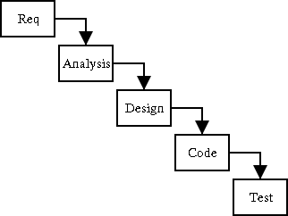
This is a very satisfactory process where requirements are well designed and not expected to change, for example automating a well proven manual system.
The weaknesses of this approach show with less well defined problems. Invariably some of the uncertainties in the requirements will not be clarified until well into the analysis and design, or even code phases, requiring backtracking to redo work.
The worst aspect of this, is that working code does not become available until near the end of the project, and very often it is only at this stage that problems with the original requirements (for example with the user interface) become apparent.
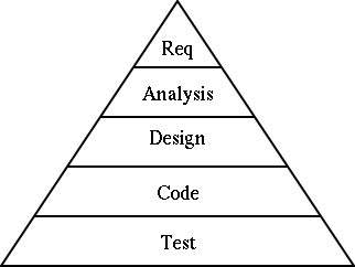
This is exacerbated, by each successive stage requiring more effort, than the previous, so that the costs of late problem discovery are hugely expensive. This is illustrated by the pyramid in Figure 2.2, “Effort involved in the steps of the waterfall process”.
The waterfall process is still probably the dominant design process. However because of its limitations it is increasingly replaced by iterative processes, particularly for projects where the requirements are not well defined.
In recent years a new approach has been used, which aims to get at least part of the code up and running as quickly as possible, to bring discovery of problems forward in the development cycle.
These processes use a series of “mini-waterfalls”, defining a few requirements (the most important) first, taking them through analysis, design and build to get an early version of the product, with limited functionality, related to the most important requirements. Feedback from this can then be used to refine the requirements, spot problems etc before more work is done.
The process is then repeated for further requirements to construct a product with a step up in functionality. Again further feedback can be applied to the requirements.
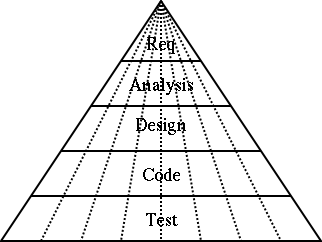
The process is repeated, until eventually all requirements have been implemented and the product is complete. It is this iteration that gives these processes their name. Figure 2.3, “Effort involved in the steps of an iterative process” shows how this process compares to the pyramid structure of the Waterfall Process.
The growth in popularity of iterative processes is closely tied to the growth of OOA&D. It is the clean encapsulation of objects that allows a part of a system to be built with stubs for the remaining code clearly defined.
Perhaps the best known Iterative Process is the Rational Unified Process (RUP) from Rational Software ( www.rational.com).
This process recognizes that our pyramid view of even slices of the waterfall is not realistic. In practice the early iterations tend to be heavy on the requirements end of things (you need to define a reasonable amount even to get started), while the later iterations have more of their effort in the design and build areas.
RUP recognizes that iterations can be grouped into a number of phases according to their stage in the overall project. Each phase may have one or more iterations.
In the inception phase iterations tend to be heavy on the requirements/analysis end, while any build activity may be limited to emulation of the design within a CASE tool.
In the elaboration phase iterations tend to be completing the specification of the requirements, and starting to focus on the analysis and design, and possibly the first real built code.
In the construction phase iterations are more or less completed with the requirements and analysis, and the effort is mostly in design and build.
Finally, in the deployment phase iterations are largely about build activity, and in particular the testing of the software.
![[Note]](images/note.png) | Note |
|---|---|
It should be clear that testing is an integral part of all phases. Even in the early phases the requirements and design should be tested, and this is facilitated by a good CASE tool. | |
We shall use an iterative process in this manual, that is loosely based on the RUP.
A good rule of thumb is that an iteration should take between six and ten weeks for typical commercial projects. Any longer and you have probably bitten off too many requirements to do in one go. You also lose focus on getting the next working iteration completed. Any shorter and you probably haven't got enough requirements to make a significant advance, and will struggle to get all the work done.
This then begs the question of how many iterations in total. This depends on the size of project. Take the estimated time (and working out/guessing that is a whole subject on its own), and divided it into 8 week chunks. Experience seems to suggest that the iterations will divide in the ratio of around 1:2:3:3 into RUP style inception, elaboration, construction and deployment phases. A project that has great vagueness in its specification (some advanced research projects for example) will tend to be heavier on the early phases.
When building a product to contract for a customer the end point is well defined. However when developing a new product for the market place, a strategy that can be used is to decide the product launch date, and hence the end date for completion of engineering (some time before). The time is then divided into iterations, and as much of the product as can be built in that time developed. The iterative process is very effective where time to market is more important than the exact functionality.
Very few software systems are conceived as monolithic artifacts. They are broken down into subsystems, modules etc.
Software processes are the same, with early parts of the process defining a top level structure, and the process reapplying to parts of the structure in turn to define ever greater details.
For example the initial design of a telephone system might identify objects to i) handle the phone lines, ii) process the calls, iii) manage the system and iv) bill the customer. The software process can then be reapplied to each of these four components to identify their design.
OOA&D with its clean boundaries to objects, naturally supports this approach. Such OOA&D with recursive development is sometimes abbreviated as OOA&D/RD.
Recursive development can be applied equally well to waterfall or iterative processes. It is not an alternative to them.
For the purpose of this manual we will use a stripped down iterative process with recursive development, loosely akin to RUP. The case study will take us through the first iteration, although at the end of the tutorial section of the manual we will look at how the project will develop to completion.
Within that first iteration, we will tackle each of the requirements capture, analysis, design and build activities in turn. Not all parts of the process are based on UML or ArgoUML. We will look at what other material is needed outside.
Within this process we will have an opportunity to see the various UML diagrams in use. The full range of UML diagrams and how they are supported is described in the reference manual (see Section 15.6, “Diagram” ).
Our requirements capture will use the UML concept of Use Cases. Starting with a Vision Document we will see how Use Cases can be developed to describe all aspects of the system's behavior in the problem domain.
During the analysis stage, we will introduce the UML concept of classes to allow us to build a top level view of the objects that will make up the solution—sometimes known as a concept diagram.
We will introduce the UML sequence diagram and statechart diagram to capture requirements for the overall behavior of the system.
Finally we will take the Use Cases from the requirements capture stage, and recast them in the language of the solution domain. This will illustrate the UML ideas of stereotyping and realization.
We use the UML package diagram to organize the components of the project. We then revisit the class diagram, sequence diagram and statechart diagram, to show how they can be used recursively to design the complete solution.
During this part of the process, we need to develop our system architecture, to define how all the components will fit together and operate.
Although not strictly part of our process, we'll look at how the UML collaboration diagram can be used as an alternative to, or to complement the sequence diagram. Similarly we will look at the UML activity diagram as an alternative or complement to the statechart diagram.
Finally we shall use the UML deployment diagram to specify how the system will actually be realized.