A Scalable, Reusable Infrastructure
Software development tools are complex software systems that are difficult to build. CASE tools must include detailed design representations, sophisticated user interface elements, and bindings to specific programming languages. These tools are difficult to build in a research setting because of the effort and breadth of understanding required. Yet, research on CASE tools is needed to produce better and more usable tools. One of the goals of my work is to provide an infrastructure for further development of CASE tools in research settings.
My approach to providing a CASE tool infrastructure consists of three main elements: (1) I developed frameworks for several aspects of the CASE tool application domain; (2) I demonstrated the use of these frameworks in a useful CASE tool; and, (3) I organized an open source development project that has brought together and facilitated the work of researchers interested in CASE tool development. This chapter explains the frameworks that make up Argo/UML's infrastructure.
"A framework is a collection of abstract and concrete classes and the interface between them, and is the design for a subsystem" (Wirfs-Brock and Johnson, 1990). Abstract classes are classes that provide only a partial implementation of the interface that they declare. Each abstract class must be subclassed with concrete classes that completely implement the declared interface. Frameworks embody knowledge about the application domain and outline an appropriate implementation while still avoiding commitment to particular implementation details. Pree (1995) emphasizes that every reusable software artifact consists of parts that remain constant across uses and parts that are adapted to a particular application. In each of the frameworks discussed below, I have kept a clear distinction between the abstract classes in the framework that provide reusable infrastructure and the concrete classes in Argo/UML that specialize that framework.
I chose the framework approach over several alternative approaches described in the literature (e.g., Krueger, 1992) because class frameworks present a low barrier to reuse: the framework approach is well known to many object-oriented software designers and requires no special tool support. The result has been widely successful in the case of my graph editing framework. I have also successfully reused my Argo critiquing framework in several design tools. The frameworks for navigational perspectives, checklists, and code generation have yet to be reused outside of Argo/UML.
Graph Editing Framework
Introduction
All of the diagram display and editing features in Argo/UML and Argo/C2 are implemented as part of a reusable Java framework called GEF (Graph Editing Framework). Work on GEF began in Spring 1996 and the first version was released via a web site later that year. Since then, GEF has evolved substantially and has been used in dozens of research projects. GEF currently consists of about 24,000 lines of Java code in 160 classes. Argo/UML's implementation of five diagram types (class, state, use case, activity, and collaboration) extends GEF with an additional 10,000 lines in 56 classes.
Many software engineering tools include connected graphs in their user interfaces, and many researchers have developed connected graph editors. Two notable class frameworks for diagram and graph editing are HotDraw (Beck and Johnson, 1994) and Unidraw (Vlissides and Linton, 1990). GEF takes this previous work into account but emphasizes extensibility, simplicity, and a high-quality user experience. HotDraw and Unidraw both achieve great extensibility by using flexible, abstract concepts. I limited the number and flexibility of GEF's concepts to make the framework more understandable. Over time, GEF has been applied to many diagram types and its look and feel provide a better user experience, but these extensions have not required a generalization of GEF's basic concepts.
Design Overview of GEF
See UML class diagram of GEF gives an overview of GEF's design. There are six major concepts in GEF. (1) The Editor class acts as a mediator that holds the other pieces together and routes messages among them. (2) Figs (short for figures) are the primitive shapes; for example, FigCircle draws a circle and FigText draws text. (3) Layers contain Figs in back-to-front order. (4) Selections keep track of which Figs are selected and the effect of each handle; for example, SelectionResize allows the bounding box of a Fig to be resized, while SelectionReshape allows individual points of a FigLine or FigPoly to be moved. (5) Cmds (short for commands) make modifications to the Figs; for example, CmdGroup removes the selected Figs from their Layer and adds a new FigGroup in their place. (6) Modes are objects that process user input events (e.g., mouse movement and clicks) and execute Cmds to modify the Figs; for example, dragging in ModeSelect shows a selection rectangle, while dragging in ModeModify moves the selected objects. I have made central those concepts that are familiar to diagram editor users and avoided those that are unfamiliar or too abstract; for example, GEF does not use the decorator pattern (Gamma et al., 1995) or attempt to offer general purpose constraint solving (e.g., Sannella, 1994).
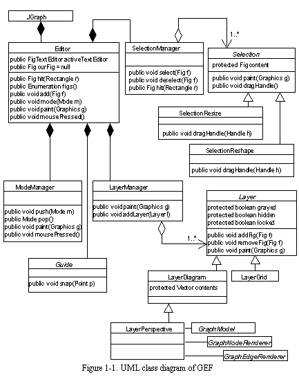
Initially, I implemented a generic connected graph representation as the underlying model for GEF diagrams. After using GEF in several applications, I found that most applications have existing data structures that can be interpreted as graphs. For example, Argo/UML has the UML meta-model and Prefer had its own data structure to represent state-based requirements. In the revised GEF, GraphModels manage the mapping from Figs in a diagram to application objects in an underlying data structure. GraphModels themselves do not hold much data; rather, they interpret existing data structures as graphs. For example, StateDiagramGraphModel interprets UML States as nodes and UML Transitions as edges. GEF's GraphModels are analogous to mediators found in Java's Swing user interface library. For example, Swing tree widgets use TreeModels and table widgets use TableModels to interpret underlying data structures as trees or tables.
Rather than represent diagrams as nodes and edges, GEF represents diagrams as ports, nodes, and edges. Ports are connection points on nodes, and edges go from a source port to a destination port. The inclusion of ports in the graph model was inspired by my previous experience with OBPE (Robbins et al., 1996). Some diagram types assign semantics to the point where an edge meets a node. Ports allow GEF to represent the semantics of these diagram types. For example, Argo/C2 represents a C2 component as a node and the top and bottom interfaces of the component as two ports. Most UML diagrams do not assign meaning to the point where an edge meets a node. In these cases, Argo/UML uses a single, invisible port that is the same size and shape as the overall node.
Implementation of Multiple Diagrammatic Views
Like many user interface systems, GEF loosely follows the Model-View-Controller (MVC) design pattern to support multiple views (Krasner and Pope, 1988; Gamma et al., 1995). As with many MVC implementations, GEF sometimes combines the view and controller roles into the same object. GEF's GraphModels play the role of the model: they provide access to the semantic state of the diagram and send notification messages when that state changes. Layers and Figs act as models for the visual properties of the diagram, including coordinates, colors, and back-to-front ordering. GEF's Editors, Layers, and Figs provide most of the functionality of the view role by displaying the diagram. Other view functionality is provided by GEF's Modes and Selections, which also contribute graphics for interaction feedback. GEF's Modes and Selections primarily play the role of controller; however, GEF provides the option for Figs and model elements to perform some event handling.
GEF uses composition structures for models, views, and controllers. CompoundGraphModel is an abstract class that combines simple graph models into more complex ones. Layers and FigGroups (including FigNodes) are compositions of views (i.e., Figs). GEF's ModeManager is composed of several controllers (i.e., Modes). The ModeManager is unusual in that it maintains a stack of active Modes rather than a single current Mode. Each Mode in the stack is asked to handle an incoming event until one of them successfully handles it. The last-in-first-out nature of the stack supports temporary Modes, such as ModeBroom, that are pushed onto the stack to process events in a short interaction and then popped off.
The MVC design pattern is an extension of the Observer-Observable design pattern (Gamma et al., 1995). In MVC, the model plays the role of an observable object that sends notifications of changes, and the view plays the role of an observer that reacts to these change notifications. GEF uses the Observer-Observable pattern at three levels:
- GEF's Figs and Layers act as observables for Editors to observe. This allows multiple diagram windows to show the same diagram. Multiple windows on the same diagram are not often used, but carefully implementing this feature avoids potentially confusing inconsistencies when multiple windows are used. For example, a designer using Argo/UML may create a new view of a diagram by double clicking on the "As Diagram" tab. This displays the diagram in the main pane of the Argo/UML window and also in a new, larger diagram window.
- GEF's GraphModels act as observables for GEF's Figs and Layers to observe. This allows for multiple diagrammatic views of the same connected graph. Each of these views may show a different projection of the connected graph and may use a different notation. For example, one Argo/UML class diagram may show some of the classes in a given package and another may show a partially overlapping set of classes in the same package. Argo/UML does not take advantage of GEF's ability to use different kinds of Figs to present the same GraphModel elements, but that feature could be used to support alternative notations such as OMT (Rumbaugh et al., 1991), or the Booch Notation (Booch, 1991).
- An application's underlying data structures (e.g., Argo/UML's implementation of the UML meta-model) act as observables for GEF's GraphModels to observe. This allows the same design representation to be viewed and edited in very different ways. For example, the dual of a graph could be edited via an alternative GraphModel that interprets data structure elements as edges rather than nodes and nodes rather than edges.
Implementation of the Broom Alignment Tool
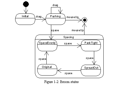
The broom alignment tool is a fairly straightforward extension to the basic GEF classes. The broom is implemented as a subclass of class Mode that interprets mouse movements and keystrokes as commands that change the position of the broom and move graph nodes that are on the face of the broom. A state machine for the broom mode is shown in See Broom states , and each state is explained in See Description of broom states .
Implementation of Selection-Action Buttons
Selection-action buttons are implemented as a fairly straightforward extension to GEF's Selection classes. Class SelectionWButtons implements the display and click-or-drag behavior of all selection-action buttons, while the subclasses of SelectionWButtons define the buttons that are appropriate to each particular type of object.
The selection-action buttons are treated the same way that resizing handles are treated: when ModeModify detects that the user has clicked or dragged on a handle it sends a message to the SelectionWButtons object asking it to process the event. When a selection-action button is clicked, a new node is created along with an edge between the current node and the new node. When a selection-action button is dragged, a new ModeCreateEdgeAndNode is created and pushed onto the ModeManager's stack. ModeCreateEdgeAndNode draws a rubberband line while the user drags and then creates a new edge and possibly a new node when the mouse button is released.
Argo Kernel
Introduction
The Argo kernel is a class framework that provides infrastructure for knowledge support features in applications such as Argo/C2, Prefer, and Argo/UML. An earlier Smalltalk-80 version of this critiquing framework was used in the Stargo OMT tool and the initial version of Argo/C2. The framework focuses on representation and algorithms that support design critics, criticism control mechanisms, checklists, the dynamic "to do" list, clarifiers, non-modal wizards, design history, and a user model.
The Argo kernel currently consists of just under 5000 lines of Java code in 34 classes. Argo/UML specializes the Argo kernel with classes for 74 critics, 6 wizards, and 3 clarifiers totaling 8300 lines of Java source code. Argo/UML also defines 11 checklists totaling just over 1000 lines.
Design Overview of the Argo Kernel
See Classes implementing the Argo kernel gives an overview of the Argo kernel's design. The key classes are Designer, Agency, Critic, ControlMech, ToDoItem, ToDoList, and History. A single instance of class Designer represents the user of the design tool; it includes identifying information, preferences, a ToDoList, and a user model. Class Agency is a utility class that provides methods for scheduling and applying critics. Design critics are instances of class Critic, while criticism control mechanisms are instances of class ControlMech. Argo's critic scheduling algorithm involves the Agency, critics, and control mechanisms; it is described in the next section. Critics produce ToDoItems when they detect design improvement opportunities. ToDoItems are stored in the designer's ToDoList. A single instance of class History stores a time-ordered list of HistoryItem objects; a given HistoryItem object can store information about a criticism that was raised, a criticism resolution, or a design manipulation.
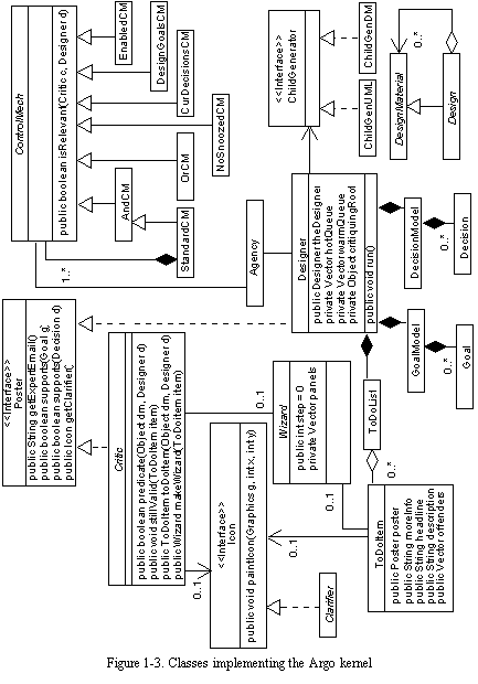
Class Wizard and interface Clarifier enhance the basic Argo kernel by providing reusable infrastructure for non-modal wizards and clarifiers, respectively. Clarifier is an interface, i.e., a Java language construct similar to a class, but consisting only of method declarations without bodies. Clarifier builds on a standard Swing interface for displaying icons and adds methods to detect when the mouse is over the clarifier. Clarifiers are implemented using the Singleton pattern to avoid the overhead of being allocated and freed each time new clarifiers are needed (Gamma et al., 1995). Since they are shared singletons, clarifiers hold no long-term state information about the design element or ToDoItem that they present, and instead, only keep that information for the duration of each display operation. Making clarifiers singletons complicates their design somewhat, but it helps maintain good interactive performance by reducing the time needed to display the currently selected design element.
The Argo critiquing framework provides a default design representation that can be used if the application does not already have a design representation data structure. Instances of class DesignMaterial represent the design elements, while instances of class Design represent the overall design or meaningful subsections. DesignMaterial instances store a dictionary of named properties and a list of observer objects needed for the DesignMaterial to play the role of observable in the Observer-Observable design pattern (Gamma et al., 1995). Applications can use class DesignMaterial directly, or make specialized subclasses if needed. In the initial version of the Argo critiquing framework, these classes played a major role and their use was required. But now, the default design representation is not used in the Prefer and Argo/UML tools because these tools have their own design representation data structures. When existing data structures are used, the application must supply a class that implements the ChildGenerator interface to allow the critiquing routines to walk the design representation. Also, existing data structures may send notification of state changes to help focus critiquing; however, critiquing will still work without change notifications, albeit more slowly.
Implementation of Design Critics and Criticism Control Mechanisms
Critics are implemented as Java classes subclassed from class Critic. Class Critic defines several methods that may be overridden to define and customize a new critic. Each critic's constructor specifies the headline, problem description, and declares relevant decision categories. The main method is predicate() which accepts a design element to be critiqued and returns true if a problem is found. Most of the critics implemented in Argo/UML go no further than overriding predicate(). However, the default methods for generating a "to do" item and a clarifier can also be overridden. Another customizable aspect of critiquing is the determination of when a previously produced "to do" item should now be removed from the "to do" list because, e.g., the identified problem has been resolved.
Criticism control mechanisms are also implemented as Java classes that implement a predicate function. However, in this case, the predicate accepts a critic rather than a design element and returns true if the critic should be enabled. Several criticism control mechanisms have been implemented and are jointly applied to the critics. All control mechanisms must agree that a critic should be enabled, otherwise, it is disabled.
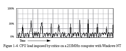
The scheduling and application of critics operate within a critiquing thread of control so as not to interrupt or delay normal user interaction with Argo/UML. The intent of the scheduling algorithm is to minimize response time to design manipulations that introduce errors and to make productive use of otherwise idle computer time. The critiquing thread executes an endless loop of three main steps: (1) recomputing the set of active critics, (2) applying critics to design elements in the "hot queue," and (3) applying critics to a few design elements in the "warm queue." The overall CPU utilization of the critiquing thread is kept to an average of approximately twenty percent. The warm queue is essentially the open list of a standard breadth-first tree traversal that starts at the object representing the entire design project and eventually touches every design element. For all but the smallest design projects, this traversal takes much longer than the desired interactive response time of about one half of a second. The hot queue contains only design elements that are likely to generate new feedback and is typically short enough to be completely cleared within half a second. Design elements are promoted to the hot queue in response to design manipulations that have the possibility of introducing problems. Application of critics to elements of the hot queue is further focused by applying only those critics that are registered as having interest in the type of design manipulation that promoted the design element.
One key trade-off in a critic scheduling algorithm is the amount of knowledge the scheduler has about each critic. With no knowledge as to what causes a particular critic to produce feedback, the scheduler can do no better than periodically applying all critics to all design elements. With complete knowledge about the analysis performed by individual critics, the scheduler can apply exactly those critics that will produce feedback as the result of a given design manipulation. Requiring less knowledge about critics helps to keep the scheduler simple and reduces the development effort needed to add a critic. Providing more knowledge about critics allows the critiquing system to work more efficiently and reduces application times. The Argo critiquing framework requires that all critics register interest in specific types of design elements and allows critics to register interest in specific types of design manipulations. If the critic author chooses not to specify which design manipulations should trigger the critic, or does so incorrectly, the critic will still be applied eventually.
The approach to implementing critics described above is somewhat similar to the way expert systems are implemented (Lee, 1990; Subramanian and Adam, 1993). I have chosen a set of trade-offs based on experience with building and using design support systems. My approach also allows critic authors to use a standard programming language rather than a limited rule language. Critics are allowed to have their own state, arbitrary side effects, and may even invoke native executables or communicate with external servers. This allows critic authors to repackage existing analysis tools as critics. In contrast, most expert system rule languages or constraint languages do not offer these possibilities. One possible extension to this framework would be to extend the general critiquing framework with specific support for a rule or constraint language, such as OCL (Object Constraint Language) (Warmer and Kelppe, 1999).
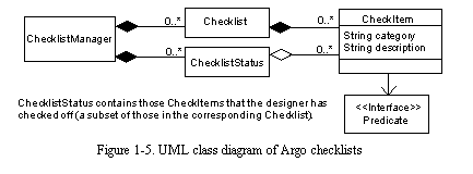
Implementation of Checklists
Argo's implementation of checklists is somewhat similar to its implementation of design critics, however, checklists are much simpler. The key classes implementing checklists are shown in See UML class diagram of Argo checklists . The CheckManager is a utility class that keeps track of all known checklists and the status of each. The checklist viewer uses the CheckManager to find the checklist that is appropriate for the currently selected design element. An instance of class Checklist contains a collection of CheckItems. Each CheckItem instance has a category string, a description string, and a guard predicate. The predicate object implements a method predicate() that determines whether that CheckItem will be displayed to the user. ChecklistStatus instances keep track of which items in a checklist have been marked as already considered by the designer.
Unlike critics, checklist items provide more general advice and they are almost always displayed to the user; i.e., their guard conditions are almost always true. The evaluation of checklist item guard conditions is not scheduled, instead it is done whenever the designer changes the currently selected design element. A possible improvement would be to only evaluate those guards for checklists that are visible on the screen.
Implementation of Wizards
Class Wizard is an abstract base class for non-modal wizards. It provides some code to implement features common to all wizards and declares some methods without providing method bodies; actual wizards must implement these methods with code specific to each wizard.
All non-modal wizards consist of a set of user interface panels that are constructed as needed when the designer presses the "Next>" button to move on to the next step of the wizard. By convention step zero is the problem description of the ToDoItem, step one is the first panel displayed after the user presses "Next>", and so on. The problem description panel is not stored in this wizard, only the panels that are specific to the wizard are stored. This allows for the designer to rapidly browse many "to do" items without incurring the overhead of creating wizard panels that may never be used.
Specific wizards are implemented as subclasses of class Wizard. These subclasses construct user interface panels for each step of the wizard as needed, implement predicates that enable or disable the "Next>" and "Finish" buttons, and implement the actions to be taken when the designer moves from step to step. On each forward step (the "Next>" button), class Wizard calls doAction() if the current step has never been completed before, and redoAction() if the designer has backed up and is now moving forward through a previously completed step. On each backward step (the "<Back" button), class Wizard calls undoAction() to reverse the effects of a previous doAction() or redoAction(). Specific wizards must implement doAction(), redoAction(), and undoAction() as appropriate, but they do not need to implement the logic that maps buttons to actions or determines when a step has previously been completed.
Views and Navigation
Introduction
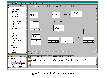
See Argo/UML main window shows the Argo/UML main window. This section discusses the implementation of several of Argo/UML's non-diagrammatic design views.
A recurring theme in the implementation of Argo/UML's design views is the use of the Model-View-Controller design pattern (Krasner and Pope, 1988; Gamma et al, 1995) where the view and controller roles are played by a user interface widget, and the role of the model is played by a mediator class. These mediator classes define task-specific views of the underlying design representation and contain very little state information themselves. The use of mediator classes is one of the standard ways to use the Swing user interface library (Eckstein, Loy, and Wood, 1998). Mediator classes observe the design representation and react to change notifications by sending their own change notifications that cause the view to be redrawn.
The Argo/UML source code for views and navigation consists of about 30,000 lines of code in 193 classes. The majority of that code is reusable infrastructure in the form of base classes and utility classes; the remainder of the code specializes the reusable infrastructure to the UML meta-model and the object-oriented design task.
Design Overview of Argo/UML Views and Navigation
Figures See Classes implementing Argo/UML's "to do" list through See Classes implementing Argo/UML's opportunistic search utility show UML class diagrams of the implementation of Argo/UML's views. The main window is implemented by class ProjectBrowser which consists of four panes: the navigator pane which shows navigational perspectives, the editor pane which shows diagrams and table views, the details pane which contains several tabs showing details of the selected design element, and the "to do" pane which presents feedback from critics using a dynamic "to do" list metaphor. The navigation pane, "to do" pane, and table views are discussed below. Secondary windows, such as the search window, are accessed through menu items in the menus of the main window.
The four main panes are always present in Argo/UML. The specific tabs shown in the editor pane and the details pane, however, are determined at system start-up time by a configuration file. Class ConfigLoader parses the configuration file and loads the classes that implement the various tabs. Each line of the configuration file contains a list of alternative tab classes, which ConfigLoader attempts to instantiate. Using a configuration file allows new tabs to be added or existing tabs to be removed without recompiling Argo/UML.
Providing alternative implementations of some tabs allows Argo/UML to run in a somewhat degraded mode if requested library classes are not available. For example, the "Source" tab displays the Java source code that will be generated for the selected model. If Argo/UML is running in the JDK (Java Development Kit) environment, the source code will be colorized (keywords, strings, and comments are shown in different colors), but if Argo/UML is running in the JRE (Java Runtime Environment), the source code will be shown in black text only. In the example, the degraded mode is needed because the JRE does not provide the Java parsing library classes needed for colorization.
Implementation of Navigational Perspectives
Navigational perspectives are implemented as combinations of child generation rules. Argo/UML uses the Swing user interface library, which defines a TreeModel interface for use with its tree widget. Each TreeModel object implements methods to access or compute the children of a given tree node. Argo/UML adds a TreeModelComposite class to combine TreeModels and defines a set of approximately thirty traversal rules, each of which is itself a simple TreeModel.
Each of the traversal rules also includes two methods used to check the composition of navigational perspectives: prerequisite and provided. The prerequisite method returns a set of design element types, one of which must already be present in the set of types that the perspective can generate. The provided method returns a set of design element types that can be generated by the rule. For example, the "Class->Initial States" rule has Class in its prerequisite set and State in its provided set. All navigational perspectives start at the object representing the entire design project and include Project in the set of design element types that can be reached. The addition of each rule adds to the set of reachable types. Rules with prerequisites that do not intersect the set of reachable types cannot be legally added and cause the rule addition button in the configuration window to be disabled.
Argo/UML uses standard JavaBeans event notifications to keep the navigator pane up-to-date when the design changes. As the designer expands or collapses the tree, the navigator pane adds or removes itself from the listener sets of the newly displayed or hidden design elements. When a design element changes state, it sends an event that causes the navigator pane to recompute the children of that element according to the current navigational perspective and to update the screen. This algorithm can be made scalable because it only needs to expend effort on tree nodes that are visible on the screen, regardless of the size of the design, the number of possible design perspectives, or the depth of the tree.
Implementation of the Dynamic "To Do" List and Clarifiers
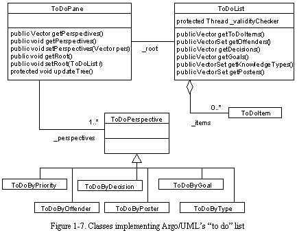
See Classes implementing Argo/UML's "to do" list shows the classes that implement the dynamic "to do" list. The "to do" list perspectives are implemented in much the same way as the navigational perspectives. However, the "to do" list perspectives are optimized for addition or deletion of items in batches, because the critiquing and item resolution threads work in cycles that produce batches of "to do" items.
Clarifiers are associated with the critics that produce each feedback item. The set of clarifiers to be displayed on a selected design element is computed simply by scanning the "to do" list for items that apply to the element, and drawing the clarifiers of the associated critics.
Implementation of Opportunistic Table Views
Argo/UML's table views are implemented by the classes shown in See Classes that implement Argo/UML's table views . TablePanel is a base class for specific table views. It provides features common to all table views, including the labels and widgets at the top of the view that display the name of the view, show the number of rows, and allow the designer to change table perspective or configure the table or row filter. 1 JSortedTable is a specialized version of the standard Swing table widget that allows the user to sort the table by clicking on a column heading. Specific table views (e.g., TablePanelUMLClassDiagram) define the set of table perspectives (e.g., classes as rows or associations as rows) and any secondary tables (e.g., the tables of attributes and associations for the selected class).
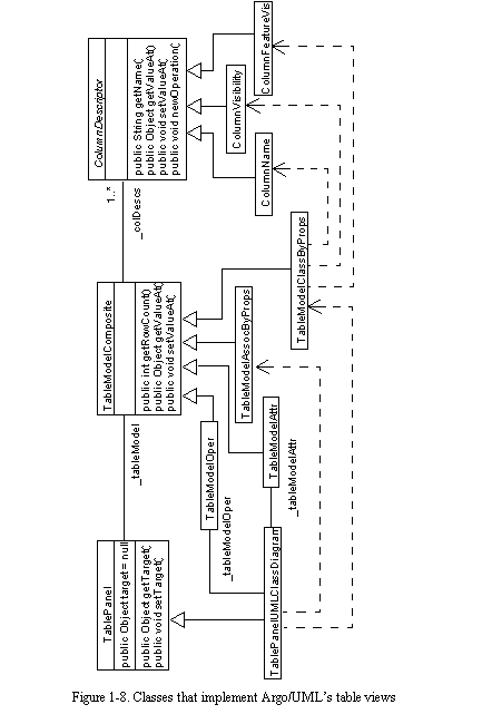
Table perspectives are implemented as subclasses of class TableModelComposite, which implements the Swing TableModel interface by combining several column descriptors. For example, TableModelStateByProps consists of column descriptors for the name of the state, its entry and exit actions, its parent state, and its stereotype. ColumnDescriptor is an abstract base class for specific column descriptors. It keeps track of the column name, the type of value that will be displayed, and whether the table cells in that column should be editable. Specific column descriptors, such as ColumnName, implement accessor methods to get or set the appropriate value in a row object. Argo/UML currently provides thirty column descriptors to access the most commonly used model attributes; a set of approximately one hundred column descriptors would provide complete access to all of the attributes defined in the UML semantics specification (OMG, 1997).
Implementation of Opportunistic Search
See Classes implementing Argo/UML's opportunistic search utility shows the classes that implement Argo/UML's opportunistic search utility. Class FindDialog defines the layout of the widgets in the search window. Each widget in the top part of the window contributes a predicate object that is used to select search results. For example, the name field contributes a PredicateStringMatch object that selects only model elements with names that match the pattern entered in the name field. The individual predicates are combined into a PredicateFind object that performs a logical-and to select only those model elements that satisfy all predicates.
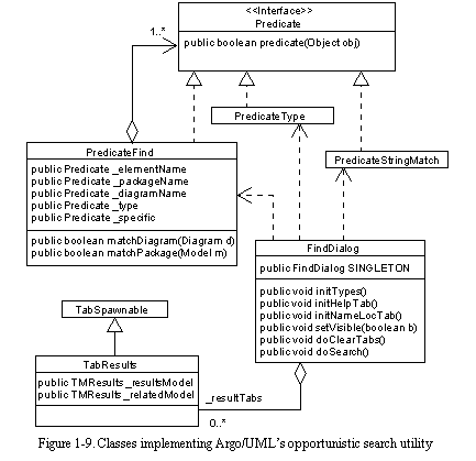
When the designer presses the "Search" button, a new TabResults is created to perform the search and display the results. The TabResults appears as a new tab in the lower half of the search window. TabResults defines two tables: one for the search results and one for model elements related to the selected search result. The search result table is filled by traversing the design and applying the search predicate to each model element. The traversal is pruned if the designer specifies constraints on the packages or diagrams to be searched. The related elements table is filled by applying the rules in class ChildGenRelated. The rules in ChildGenRelated are currently implemented as Java code; a possible extension of this part of Argo/UML's infrastructure would allow designers to specify rules in a language such as OCL (Warmer and Kelppe, 1999).
Design Representation and Code Generation
Introduction
The preceding sections have described how Argo/UML presents design information to the user and provides knowledge support. This section covers how Argo/UML represents design elements internally and in external file formats.
Design Overview of Design Representation and Code Generation
Figures See Some UML meta-model classes through See UML class diagram of classes for code generation. show some of the classes that implement Argo/UML's design representation and the classes involved in processing model files and generating source files.
A recurring theme in this section of Argo/UML's implementation is the use of appropriate standards. UML (Unified Modeling Language) is a standard promoted by the Object Management Group (OMG, 1997). XML (Extensible Markup Language) is a standard for structured file formats promoted by the World-Wide-Web Consortium (W3C, 1998). XMI (XML Model Interchange format) is a standard way of storing UML designs in XML files and is also promoted by the Object Management Group (OMG, 1998). PGML (Precision Graphics Markup Language) is a standard XML file format promoted by the World-Wide-Web Consortium for representing graphics that consist of primitive graphical elements such as lines, rectangles, and text (W3C, 1998). As will be further discussed in Chapter 9, leveraging standards guides development and reduces the need to develop and document new approaches.
Implementation of the UML Meta-Model
The UML standard consists of three main specifications: a notation guide that specifies the visual appearance of UML diagrams, a semantics specification that details the UML meta-model, and the OCL (Object Constraint Language) specification that adds a first-order predicate logic language for expressing constraints on UML models. The UML meta-model is itself a UML model that specifies how a UML design can be represented.
See Some UML meta-model classes show some of the classes that implement Argo/UML's version of the UML meta-model. These classes were initially generated from a Rational Rose(tm) model provided with the UML 1.1 standard. As a result, Argo/UML strictly adheres to the UML standard, including all the names of packages, meta-classes, attributes, and associations. Leveraging the standard saved development resources that are very limited in an academic setting. Furthermore, strict adherence made it easier to support the XMI standard, which is itself generated from the UML standard.
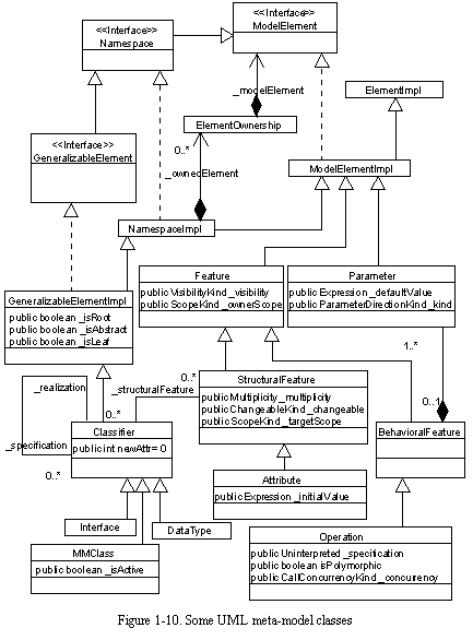
Limited modifications were made to the meta-model to make it fit the Java language and the GEF library. For example, multiple inheritance used in the standard meta-model was replaced with Java interfaces and single inheritance; also, an assumption in GEF required the addition of a Realization meta-class that is analogous to the Generalization meta-class. Fortuitously, recent changes to the UML standard match Argo/UML better than the earlier version (OMG, 1999).
Argo/UML's implementation of the UML meta-model uses JavaBeans-style method naming and change notifications. For example, the attribute "concurrency" of meta-class Operation in the UML meta-model is accessed with methods getConcurrency() and setConcurrency() in the Argo/UML implementation. Also, whenever the concurrency of an operation is changed, a standard JavaBeans property change event is fired with information about the name of the property that changed, its old value, and its new value.
Argo/UML's implementation of the UML meta-model consists of 9900 lines of Java source code in 103 classes. Test cases based on the examples in the UML specification add another 1800 lines in 15 classes.
Implementation of XMI and PGML File Formats
Argo/UML uses XMI files to store design representations. Using the XMI standard has helped keep the focus of Argo/UML on cognitive issues by allowing issues of interoperability, version control, and repositories to be deferred. Argo/UML uses IBM's XML parser to read XMI files using a straightforward set of tag handlers. It generates XMI files using a new "little language" called TEE (Templates with Embedded Expressions). One TEE template is associated with each meta-class and consists of plain text to be echoed to the output file and embedded OCL (Object Constraint Language) expressions. Each OCL expression is evaluated with respect to a design element and results in a bag of objects. Each result object is output in sequence and may use its own template. See Some TEE templates for generating XMI files gives two simplified examples of the TEE templates used to generate XMI.
I chose not to use XMI's ViewElement, presentation, geometry, and style tags to represent diagrams. Instead, Argo/UML uses the PGML (Precision Graphics Markup Language) standard file format for diagrams (W3C, 1998). This has the advantage of being better defined and may allow users to view Argo/UML diagrams in future web browsers.
The UML standard is still evolving and the XMI standard is evolving with it. The UML 1.4 specification will be released next year with a new draft of the XMI specification. Further revisions to UML are scheduled over the next few years. PGML has also evolved and has now been superseded by SVG (Scalable Vector Graphics) (W3C, 1999). The template expansion technique and TEE files are expected to make upgrading Argo/UML's file generation capabilities fairly easy.
The TEE file format and the use of embedded OCL expressions has proven remarkably flexible and useful, despite the fact that only a small subset of OCL is supported. One possible extension to the Argo/UML system would be to generate HTML reports to document designs on the web. Another extension would be to replace the code generation scheme discussed below with a more customizable one. Both of these can be accomplished with TEE files.
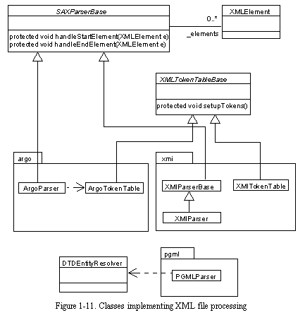
See Classes implementing XML file processing shows the classes that implement Argo/UML's XML file parsing. Altogether, Argo/UML's code to parse and generate XMI and PGML files consists of 4000 lines of Java code in 8 classes, 3 XML DTD (Document Type Definition) files totaling 3900 lines, and 3 TEE files totaling 2000 lines.
Implementation of Code Generation
See UML class diagram of classes for code generation. shows the Argo/UML classes involved in code generation. Code generation in Argo/UML is supported with a language independent abstract base class and Java-specific subclasses. Class Generator is an abstract base class that is similar to the Visitor design pattern (Gamma et al., 1995). However, the logic to traverse the design representation is intermixed with node processing logic. Class GeneratorJava is a Java-specific subclass that generates Java source files. Class GeneratorDisplay generates simplified Java code to be displayed in the "Source" tab and in the textual labels of UML class icons and other parts of UML diagrams.

Each of the Java-specific classes implements methods that generate source code for design elements of a given type. Since the code generation logic is coded in Java, the only way to customize it is by changing the code or by adding new code generation preferences. One possible extension to the Argo/UML system would be to use TEE files to generate source code from templates, as is done for XMI and PGML files. This would greatly ease simple customizations. For example, with templates one can easily control the indentation of the generated code or the position of opening and closing braces. Furthermore, easily customized code generation might be useful in generating code other than the classes directly modeled. For example, a designer could generate property sheets by using a set of templates that generate one user interface window for each class in a design and one widget in that window for each attribute of the corresponding class.
Altogether, Argo/UML's code generation facilities consist of 2000 lines of Java code in 7 classes.