Almost all the output of the requirements capture process is documentary. The only diagram is the use case diagram, showing the relationships between use cases and actors.
Typical sections of this document would be as follows.
Summary. A statement of the context, problem and solution goals.
Goals. What are we trying to achieve (and how do we wish to achieve it).
Market Context or Contractual Arrangements. For a market led development, this should indicate target markets, competitive differentiators, compelling events and so forth. For a contractual development this should explain the key contractual drivers.
Stakeholders. The users (in the widest sense) of the system. Many of these will map in to actors, or control equipment that maps into actors.
Key Features. At the very highest level what are they key functional aspects of the problem/desired solution. These will largely map down to the use cases. It is helpful to give some prioritization here.
Constraints. A high level view of the non-functional parameters of the system. These will be worked out in detail in the supplementary requirements specification.
Appendix. A listing of the actors and use cases that will be needed to meet this vision. It is useful to link to these from the earlier sections to ensure comprehensive coverage.
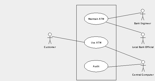
The vision document has identified the use cases and actors. The use case diagram captures how they interact. In our ATM example we have identified “customer uses machine”, “maintain machine” and “audit” as the three main use cases. We have identified “customer”, maintenance engineer“,”“local branch official” and “central computer” as the actors.
Figure 3.1, “Basic use case diagram for an ATM system” shows how this could be displayed on a use case diagram. The use cases are shown as ovals, the actors as stick people (even where they are machines), with lines (known as associations connecting use cases to the actors who are involved with them. A box around the use cases emphasizes the boundary between the system (defined by the use cases) and the actors who are external.
![[Note]](images/note.png) | Note |
|---|---|
Not all analysts like to use a box around the use cases. It is a matter of personal choice. | |
The following sections show how the basic use case diagram can be extended to show additional information about the system being designed.
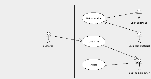
Active actors initiate interaction with the system. This can be shown by placing an arrow on the association from the actor pointing toward the use case. In the ATM example, the customer is an active actor.
Interaction with passive actors is initiated by the system. This can be shown by placing an arrow on the association from the use case pointing toward the actor. In the ATM example, the central computer is a passive actor.
This is a good example where the arrow helps, since it allows us to distinguish an event driven system (the ATM initiates interaction with the central computer) from a polling system (the central computer interrogates the ATM from time to time).
Where an actor may be either active or passive, depending on circumstances, the arrow may be omitted. In the ATM example the bank engineer fits into this category. Normally he is active, turning up on a regular cycle to service the machine. However if the ATM detects a fault, it may summon the engineer to fix it.
The use of arrows on associations is referred to as the navigation of the association. We shall see this used elsewhere in UML later on.
Figure 3.2, “Use case diagram for an ATM system showing navigation.” shows the ATM use case diagram with navigation displayed.
It can be useful to show the multiplicity of associations between actors and use cases. By this we mean how many instances of an actor interact with how many instances of the use case.
By default we assume one instance of an actor interacts with one instance of a use case. In other cases we can label the multiplicity of one end of the association, either with a number to indicate how many instances are involved, or with a range separated by two periods (..). An asterisk ( *) is used to indicate an arbitrary number.
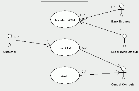
In the ATM example, there is only one central computer, but it may be auditing any number of ATM uses. So we place the label 0..* at the use case end. There is no need for a label at the other end, since the default is one.
A local bank will have up to three officials authorized to unload and load ATM machines. So at the actor end of the relationship with the use case Maintain ATM, we place the label 1..3. They may be dealing with any number of ATM machines, so at the other end we place the label 0..*.
There may be any number of customers and there may be any number of ATM systems they could use. So at each end of the association we place the label 0..*.
Figure 3.3, “Use case diagram for an ATM system showing multiplicity.” shows the ATM use case diagram with multiplicity displayed.
Multiplicity can clutter a diagram, and is often not shown, except where it is critical to understanding. In the ATM example we would only choose to show 1..3 against the local bank official, since all others are obvious from the context.
In our ATM example so far we have just three use cases to describe all the behavior of the system. While use cases should always describe a significant chunk of system behavior, if they are too general they can be difficult to describe.
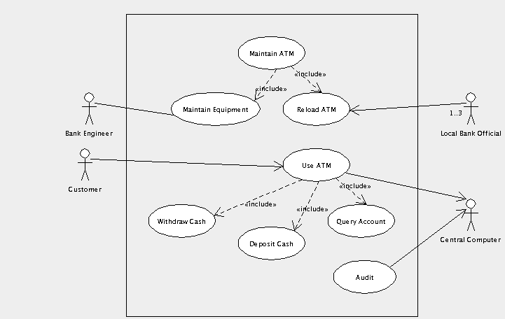
We could for example define the behavior of the use case “Use ATM” in terms of the behavior of three simpler use cases, “Deposit Cash”, “Withdraw Cash” and “Query Account”. The main use case could be specified by including the behavior of the subsidiary use cases where needed.
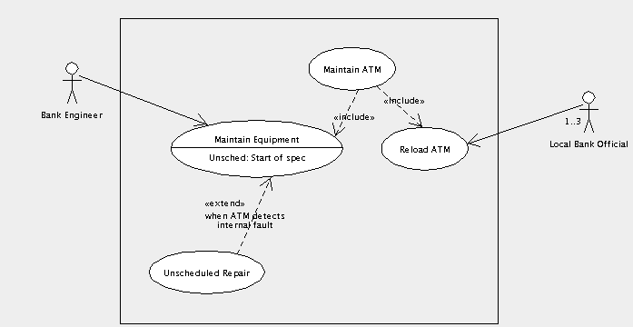
Similarly the “Maintain ATM” use case could be defined in terms of two use cases “Maintain Equipment” and “Reload ATM”. In this case the two actors involved in the main use case are really only involved in one or other of the two subsidiary use cases and this can be shown on the diagram.
The decomposition of a use case into simpler sub-use cases is shown in UML by using an include relationship, a dotted arrow from the main use case to the subsidiary, with the label «include».
Include relationships are fine for breaking down the use case behaviors in to hierarchies. However we may also want to show a use case that is an extension to an existing use case to cater for a particular circumstance.
In the ATM example we have a use case covering routine maintenance of the ATM, “Maintain Equipment”. We also want to cover the special case of an unscheduled repair caused by the ATM detecting an internal fault.
This is shown in UML by the extend relationship. In the main use case, we specify a name for a location in the description, where an extension to the behavior could be attached. The name and location are shown in a separate compartment within the use case oval. The representation extend relationship is the same as the include relationship, but with the label «extend». Alongside the extend relationship, we specify the condition under which that behavior will be attached.
Figure 3.5, “Use case diagram for an ATM system showing an extend relationship.” shows the ATM use case diagram with an extend relationship to a use case for unscheduled repairs. The diagram is now getting rather complex, and so we have split it into two, one for the maintenance side of things, the other for customer usage and audit.
The “Maintain Equipment” use case defines a name “Unsched”, at the start of its description. The extending use case “Unscheduled Repair” is attached there when the ATM detects an internal error.
Use cases may be linked together in one other way. One use case may be a generalization of a subsidiary use case (or alternatively the subsidiary is a specialization of the main use case).
This is very like the extends relationship, but without the constraint of specific extension points at which the main use case may be extended, and with no condition on when the subsidiary use case may be used.
Generalization is shown on a use case diagram by an arrow with solid line and solid white head from the subsidiary to the main use case.
This may be useful when a subsidiary use case specializes the behavior of the main use case at a large number of positions and under a wide range of circumstances.
However the lack of any restriction makes generalization very hard to specify precisely. In general use an extend relationship instead.
Each use case must be documented to explain in detail the behavior it is specifying. This document is known by different names in different processes: use case specification,use case scenario or even (confusingly) just use case.
A typical use case will include the following sections.
Name. The name of the use case to which this relates.
Goal. A one or two line summary of what this use case achieves for its actors.
Actors. The actors involved in this use case, and any context regarding their involvement.
![[Note]](images/note.png)
Note This should not be a description of the actor. That should be associated with the actor on the use case diagram.
Pre-condition. These would be better named “pre-assumptions”, but the term used everywhere is pre-conditions. This is a statement of any simplifying assumptions we can make at the start of the use case.
In the ATM example we might make the assumption for the“Maintain Equipment” use case that an engineer is always available, and we do not need to worry about the case where a routine maintenance visit is missed.
![[Caution]](images/caution.png)
Caution Avoid pre-conditions wherever possible. You need to be absolutely certain that the pre-condition holds under all possible circumstances. If not your system will be under specified and hence will fail when the pre-condition is not true. Alternatively, when you cannot be certain the pre-condition is always true, you will need to specify a second use case to handle the pre-condition being false. In the first case, pre-conditions are a source of problems, in the second a source of more work.
Basic Flow. The linear sequence of steps that describe the behavior of the use case in the “normal” scenario. Where a use case has a number of scenarios that could be normal, one is arbitrarily selected. Specifying the basic flow is described in more detail in Section 3.3.3.1, “Specifying the Basic Flow” below.
Alternate Flows. A series of linear sequences describing each of the alternative behaviors to the basic flow. Specifying alternate flows is described in more detail in Section 3.3.3.2, “Specifying the Alternate Flows”.
Post-conditions. These would be better named “post-assumptions”. This is a statement of any assumptions that we can make at the end of the use case. Most useful where the use case is one of a series of subsidiary use cases that are included in a main use case, where they can form the pre-conditions of the next use case to be included.
![[Caution]](images/caution.png)
Caution Like pre-conditions, post-conditions are best avoided. They place a burden on the specification of the use case flows, to ensure that the post-condition always holds. They therefore are also a source of problems and extra work.
Requirements. In an ideal world the vision document, use case diagrams, use case specifications and supplementary requirements specification would form the requirements for a project.
For most market-led developments, where ownership of requirements is within the same business as the team who will do the development, this is now usually the case. The marketing department can learn use case based requirements capture and analysis to link to their customer facing activities.
However for external contract developments, customers may insist on a traditional “list of features” as the basis of the contract. Where this is the case, this section of the use case specification should link to the contract features that are covered by the use case.
This is often done through a third party tool that can link documents, providing automated checking of coverage, in which case this section is not needed, or may be generated automatically.
The final size of the use case specification will depend on the complexity of the use case. As a rule of thumb, most use cases take around 10-15 pages to specify, the bulk of which is alternate flows. If you are much larger than this, consider breaking the use case down. If you are much smaller consider whether the use case is addressing too small a chunk of behavior.
All flows in a use case specification are linear—that is there is no conditional branching. Any choices in flows are handled by specifying another alternate flow that takes over at the choice point. It is important to remember we are specifying behavior here, not programming it.
A flow is specified as a series of numbered steps. Each step must involve some interaction with an actor, or at least generate a change that is observable externally by an actor. Requirements capture should not be specifying hidden internal behavior of a system.
For example we might give the following sequence of steps for the basic flow of the use case "Withdraw Cash" in our ATM example.
Customer indicates a receipt is required.
Customer enters amount of cash required.
ATM verifies with the central computer that the customer can make this withdrawal.
ATM dispenses cash to the customer.
ATM issues receipt to customer.
Remember this is a sub-use case included in the main “Use ATM” use case, which will presumably handle checking of cards and PINs before invoking this included use case.
![[Note]](images/note.png) | Note |
|---|---|
The first step is not a condition. We take as our basic flow the case where the customer does want a receipt. The case where the customer does not want a receipt will be an alternative flow. | |
This captures the alternative scenarios, as linear flows, by reference to the basic flow. Initially we just build a list of the alternate flows.
Customer does not require a receipt.
Customer's account will not support the withdrawal.
Communication to the central computer is down.
The customer cancels the transaction.
The customer fails to take the dispensed cash.
Subsequently we flesh out each alternate flow, by reference to the basic flow. For example the first alternate flow might look like.
Customer does not require a receipt.
At step 1 of the basic flow the customer indicates they do not want a receipt.
The basic flow proceeds from step 2 to step 4, and step 5 is not used.
The convention is to number the various alternate flows as A.1, A.2, A.3, etc. The steps within an alternate flow are then numbered from this. So the steps of the first alternate flow would be A.1.1, A.1.2, A.1.3, etc.
Iterative development will prioritize the use cases, and the first iterations will address the most important.
Early iterations will capture the basic flows of the most important use cases with only essential detail and list the headings of the main alternate flows.
Later iterations will address the remaining use cases, flesh out the steps on individual alternate flows and possibly provide more detail on individual steps.
This captures the non-functional requirements or constraints placed on the system. Since use cases are inherently functional in nature, they cannot capture this sort of information.
![[Note]](images/note.png) | Note |
|---|---|
Some analysts like to place non-functional requirements in a section at the end of each use case specification, containing the non-functional requirements relevant to the use case. I don't like this for two reasons. First key non-functional requirements (for example about performance) may need to appear in many use cases and it is bad practice to replicate information. Secondly there are invariably some non-functional requirements that are system wide and need a system wide document. Hence my preference for a single supplementary requirements specification. | |
There should be a section for each of the main areas of non-functional requirements. The checklist provided by Ian Sommerville in his book Software Engineering (Third Edn, Addison-Wesley, 1989) is a useful guide.
Speed. Processor performance, user/event response times, screen refresh time.
Size. Main memory (and possibly caches), disc capacity.
Ease of use. Training time, style and detail of help system.
Reliability. Mean time to failure, probability of unavailability, rate of failure, availability.
Robustness. Time to restart after failure, percentage of events causing failure, probability of data corruption on failure.
Portability. Percentage of target-dependent code/classes, number of target systems.
To this we should add sections on environment (temperature, humidity, lightening protection status) and standards compliance.
